ELECTRICAL ENGINEERING
Polarity test and parallel operation of single phase transformer.
Experiment No. : – 11
Aim of the Experiment: –
Apparatus Required: –
Circuit Diagram: –

Theory: –
Parallel operation of transformers is used for load sharing. The transformers are connected in parallel on both primary and secondary side. Following conditions to be satisfied during the parallel operation of transformers-
- Same polarities should be connected.
- The two transformers should have same voltage ratio.
- The percentage impedance should be same.
- There should be no circulating current.
Procedures: –
- Connect all the apparatus as per circuit diagram (fig. 11.1) for polarity test.
- Measure the terminal voltage. if voltage is zero then the polarity is same.
- Again connect all the apparatus as per circuit diagram (fig. 11.2) for load sharing of transformer.
- Note the meters readings as per observation table.
Observation Table: –
Precaution: –
- Transformers should be connected in such a way that they have same polarity.
- All connections should be neat and tight.
- Connecting leads should be perfectly insulated.
Conclusion: –
To be written by student.

Share this:
- Click to share on Twitter (Opens in new window)
- Click to share on Facebook (Opens in new window)

Parallel Operation of a Single Phase Transformer
Parallel Operation of a Single Phase Transformer means that the two or more transformers having the same polarities, same turn ratios, same phase sequence and the same voltage ratio are connected in parallel with each other.
The circuit diagram of two single-phase transformer A and B connected in parallel are shown below:
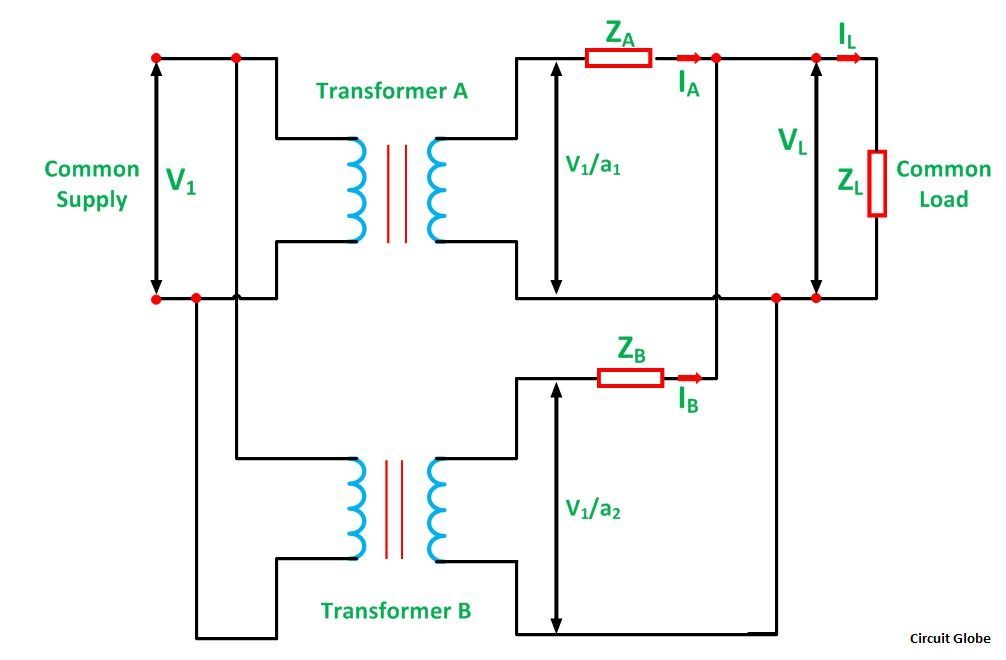
a 1 is the turn ratio of the transformer A a 2 is the turn ratio of transformer B Z A is the equivalent impedance of the transformer A referred to secondary Z B is the equivalent impedance of the transformer B referred to secondary Z L is the load impedance across the secondary I A is the current supplied to the load by the secondary of the transformer A I B is the current supplied to the load by the secondary of the transformer B V L is the secondary load voltage I L is the load current
Applying Kirchhoff’s Current Law,

By Kirchhoff’s Voltage Law,
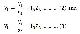
Now putting the value of I B from the equation (1) in equation (3) we will get,

Solving equations (2) and (4) we will get,
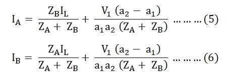
The current I A and I B have two components. The first component represents the transformers share of the load currents and the second component is a circulating current in the secondary windings of the single-phase transformer.
The undesirable effects of the circulating currents are as follows
- They increase the copper loss.
- The circulating current overloads the one transformer and reduce the permissible load kVA.
Equal Voltage Ratio
In order to eliminate circulating currents, the voltage ratios must be identical. That is a 1 =a 2
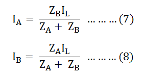
From the above equation (9), it is clear that the transformer currents are inversely proportional to the transformer impedance. Thus, for the efficient parallel operation of the two single-phase transformers, the potential differences at full load across the transformer internal impedance should be equal.
This condition ensures that the load sharing between the two single-phase transformer is according to the rating of each transformer. If the per-unit equivalent impedance are not equal, then the transformer will not share the load in proportion to their kVA ratings. As a result, the overall rating of the transformer bank will be reduced.
Equation (9) can also be written as

The current in the equations (7) and (8) is changed into volt-amperes by multiplying the two equations by the common load voltage V L .
Therefore, we know that,
The total load in volt-ampere (VA) is
The volt-ampere of transformer A is
Similarly, the volt-ampere of transformer B is
Hence, the various equations will be written as shown below
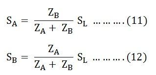
Equating the equation (11) and (12) we will get

Equation (13) tells that the volt-ampere load on each single-phase transformer is inversely proportional to its impedance.
Hence, to share the load in proportion to their ratings, the transformers should have the impedance which is inversely proportional to their ratings.
Related terms:
- Parallel Operation of a Transformer
- Parallel Operation of the Alternators
- Difference Between Single Phase and Three Phase Induction Motor
- Advantages of 3 Phase Over Single Phase System
- Difference Between Single Phase & Three Phase
3 thoughts on “Parallel Operation of a Single Phase Transformer”
Wow, nice discussion of the subject; very helpful.
It was really helpful, thanks 🙂
Leave a Comment Cancel Reply
Your email address will not be published. Required fields are marked *
Save my name, email, and website in this browser for the next time I comment.
Parallel Operation of Single Phase Transformers

By parallel operation of single-phase transformers, we mean two or more transformers are connected to the same supply bus bars on the primary side and to a common bus bar/load on the secondary side. Such a requirement is frequently encountered in practice.
Two transformers A and B connected in parallel are shown in the figure.
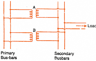
While connecting two or more than two transformers in parallel, it is essential that their terminals of similar polarities are joined to the same busbars as shown.
The wrong connections may result in a dead short-circuit and primary transformers may be damaged unless protected by fuses or circuit breakers .
Need of Parallel Operation in Single Phase Transformers
- Firstly, if one transformer fails, the continuity of supply can be maintained through other transformers.
- Secondly, when the load on the substation becomes more than the capacity of the existing transformers, another transformer can be added in parallel.
- Thirdly, any transformer can be taken out of the circuit for repair/routine maintenance without interrupting the supply to the consumers.
- Non-availability of a single large transformer to meet the total load requirement.
- The power demand might have increased over time necessitating augmentation of the capacity. More transformers connected in parallel will then be pressed into service.
- To ensure improved reliability. Even if one of the transformers gets into a fault or is taken out for maintenance/repair the load can be continued to be serviced.
- To reduce spare capacity. If many smaller size transformers are used one machine can be used as spare. If only one large machine is feeding the load, a spare of similar rating has to be available. The problem of spares becomes more acute with fewer machines in service at a location.
- When transportation problems limit the installation of large transformers at a site, it may be easier to transport smaller ones to the site and work them in parallel.
Conditions for Parallel Operation of Single Phase Transformer
- Transformers should be properly connected with regard to their polarities .
- The voltage ratings and voltage ratios of the transformers should be the same.
- The per unit or percentage impedances of the transformers should be equal.
- The reactance/resistance ratio s of the transformers should be the same.
1. Connection with regard to Polarity
The first condition for successful parallel operation of single phase transformer is that the transformers should be properly connected with regard to their polarities.
This condition is absolutely essential because wrong connections may result in dead short-circuit.
Figure (i) shows the correct method of connecting two single-phase transformers in parallel.
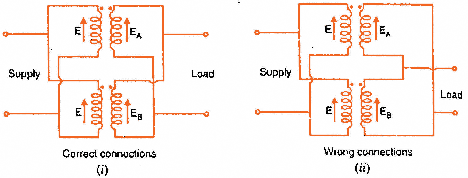
Figure (ii) shows the wrong method of connecting two single-phase transformers in parallel. Here the two secondaries are so connected that their e.m.f.s E A and E B are additive.
This may lead to short-circuiting conditions and a very large circulating current will flow in the loop formed by the two secondaries.
Such a condition may damage the transformers unless they are protected by fuses and circuit breakers.
2. Same Voltage Rating and Voltage Ratio
The next condition for parallel operation of single phase transformer is the same voltage rating and voltage ratio.
This condition is desirable for the satisfactory parallel operation of transformers.
If this condition is not met, the secondary e.m.f.s will not be equal and there will be circulating current in the loop formed by the secondaries. This will result in the unsatisfactory parallel operation of transformers.
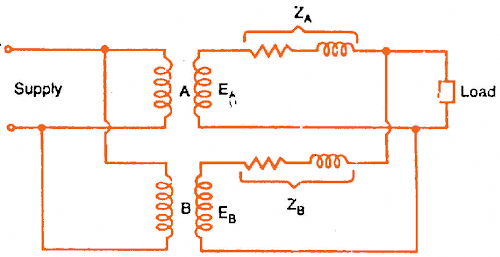
Even a small difference in the induced secondary voltages can cause a large circulating current in the secondary loop because impedances of the transformers are small. This secondary circulating current will cause current to be drawn from the supply by the primary of each transformer.
These currents will cause copper losses in both primary and secondary. This creates heating with no useful output.
When the load is connected to the system, this circulating current will tend to produce unequal loading conditions i.e., the transformers will not share the load according to their kVA ratings. It is because the circulating current will tend to make the terminal voltages of the same value for both transformers.
Therefore, the transformer with a smaller voltage ratio will tend to carry more than its proper share of the load.
Thus, one transformer would tend to become overloaded than the other and the system could not be loaded to the summation of transformer ratings without overloading one transformer.
Read: Why Transformers are Rated in KVA?
3. Equal Percentage Impedance
Another condition for parallel operation of single phase transformer is all transformers should have equal percentage impedance.
This condition is also desirable for proper parallel operation of single-phase transformers.
If this condition is not met, the transformers will not share the load according to their kVA ratings.
Sometimes this condition is not fulfilled by the design of the transformers.
In that case, it can be corrected by inserting proper amount of resistance or reactance or both in series with either primary or secondary circuits of the transformers where the impedance is below the value required to fulfill this condition.
4. Same Reactance/Resistance Ratio
If the reactance/resistance ratios of the two transformers are not equal, the power factor of the load supplied by the transformers will not be equal.
In other words, one transformer will be operating with a higher and the other with a lower power factor than that of the load.
Equal Percentage Impedance (Condition 3) is much more important than Same Reactance/Resistance Ratio (condition 4) .
Considerable deviation from Same Reactance/Resistance Ratio (condition 4) will result in only a small reduction in the satisfactory degree of operation.
When desired, condition (4) also may be improved by inserting external impedance of proper value.
Related Articles
Part 1Part 2Part 3Part 4Part 5 1. A capacitor start single phase induction motor will…
Single phase motors are the most familiar of all electric motors because they are extensively…

In today’s post, we will go through a video that explains the working of single phase and three phase transformers in detail. We have already discussed the working principle of a transformer and Why…

Read about working of induction motors here. All topics under single phase induction motor are…
Learn about the advantages and disadvantages of star-star (Y-Y) transformer connections. Discover key considerations to…

31. The type of starting relay used on single phase hermetic motor is (A) hot…
Comments are closed.
- Switch skin
Home > Electrical Machines > Transformer > Parallel Operation of Single-Phase & Three-Phase Transformers
Parallel Operation of Single-Phase & Three-Phase Transformers
Needs & conditions for parallel connection of transformers.
In a power system network , transformers are used to step up and step-down voltage levels. The rating of a transformer is selected according to the load demand. But load demand increases day by day. Hence, to meet extra load demand, we need to change the existing transformer to a higher capacity transformer or we can add an extra transformer connected with the existing transformer.
- Related Post: Parallel Operation of DC Generators

The economic way to meet load demand is to connect a second transformer in parallel with the existing transformer.
Table of Contents
Need of Parallel Operation of Transformers
The parallel operation of the transformer is needed due to following reasons.
- To supply a load of more ratings to the existing transformer, we need to connect the second transformer in parallel with the existing transformer.
- At the time of maintenance , a second transformer is used to maintain continuity of supply to the consumer. It increases the reliability of a system.
- When one transformer is in fault condition or fails to operate due to any reason, the second transformer is used to supply and avoid intrusion of power.
Related Posts:
- Difference Between Current Transformer & Potential Transformer
- Difference between Power Transformers and Distribution Transformers?
Conditions for Parallel Operation of Transformers
To ensure the successful parallel operation of the transformers, the following conditions must be satisfying.
- The primary winding of both transformers is suitably designed for the supply system voltage and frequency.
- Both transformers are connected with the same polarity. If polarities are not matched there is a chance of short-circuiting. Hence, while connecting both transformers in parallel, the polarity of both transformers must match.
- The turns ratio (transformation ratio) of both transformers should be identical. It means the voltage rating of primary and secondary windings should be identical. If the turns ratio is not the same, the parallel operation of transformers is possible. But some amount of circulating current will flow in no-load conditions. And it will create unequal loading conditions.
- In order to avoid circulating current, the X/R ratio must be the same. It means the impedance triangle must be identical for both transformers. If the X/R ratio is not the same, both transformers will operate on different power factors .
- When both transformers have different KVA ratings, the equivalent impedance is inversely proportional to the individual kVA rating (circulating current is ignored).
Parallel Operation of Single-Phase Transformer
Two single-phase transformers can be connected in parallel as shown in the figure below.
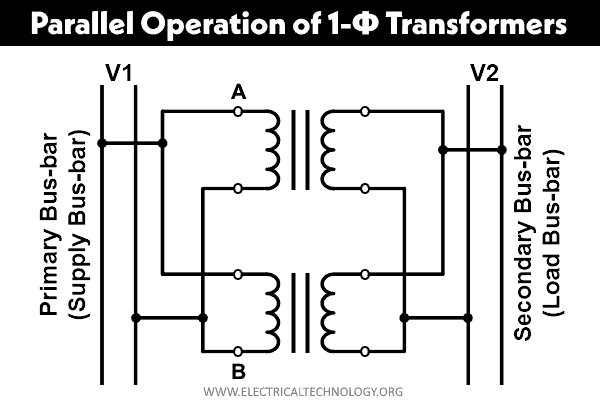
As shown in the figure, the primary winding of both transformers is connected with the supply bus bar and the secondary winding of both transformers is connected with the load bus bar. In this way, we can connect two or more than two transformers in parallel and exceed transformer ratings.
While connecting transformers in parallel, the polarities of the transformer must be matched. Otherwise, it will lead to short-circuit and may damage the transformer.
Ideal Condition
In an ideal condition, we consider both transformers have the same voltage ratio and same turns ratio. So, the impedance triangle of both transformers is identical in shape and size. The phasor diagram of this condition is as shown in the figure below.

- E = No-load secondary voltage of each transformer
- V 2 = Secondary (load) terminal voltage
- V 1 = Primary (supply) terminal voltage
- I A = Current supplied by transformer-1
- I B = Current supplied by transformer-2
- I = Total current
As shown in the phasor diagram, the total load current (I) is legging behind V 2 by an angle of ф. And current I A and I B of an individual transformer are in phase with total current (I).

And individual current (I A and I B ) for each transformer is;

Similarly, current I B is derived as;

Equal Voltage Ratios
Let’s assume that, the transformers have the same voltage ratio. Hence, no-load voltage of both transformers is equal (E A = E B = E). In this condition, no current will flow between two transformers. The equivalent circuit of this condition is as shown in the figure below.

- E A , E B = No-load voltage
- Z A , Z B = Impedances
- I A , I B = Secondary current of respective transformer
- V 2 = Terminal voltage
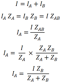
Here, the impedance of both transformers is connected in parallel. Hence, total impedance Z AB is;

Vector diagram of this condition is as shown in the figure below.

Here, current I A and I B are not in phase. Hence, the total current supplied to the load is a phasor summation of I A and I B . And total current (I) is as shown in the vector diagram. Here, we have considered that the no-load voltage of each transformer is the same and it is in-phase in the vector diagram.
Let’s assume Q A and Q B are power consumed by each transformer respectively.
Q A = V 2 I A and Q B = V 2 I B
The total power consumed by both transformers is Q;
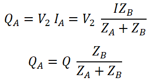
Therefore, Q A and Q B are obtained in magnitude and in-phase from the above vectorial equations.
Unequal Voltage Ratio
If the transformation ratio is not the same for both transformers, no-load secondary voltage is not the same. In this condition, some amount of current will flow between transformers in no-load conditions. This current is known as circulating current IC.

The no-load EMF of both transformers is not the same in this condition. Hence,
E A = I A Z A + I Z L
E B = I B Z B + I Z L
Z L = load impedance
I = I A + I B and V 2 = I Z L
E A = I A Z A + ( I A + I B ) Z L
E B = I B Z B + (I A + I B ) Z L
Subtract the above equations;
E A – E B = I A Z A – I B Z B
( E A – E B ) + I B Z B = I A Z A

Put the value of I A in the equation of E B ;
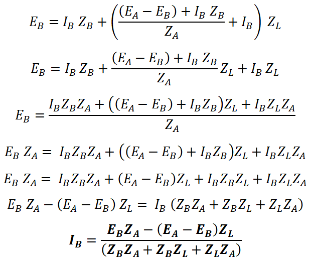
Now, put the value of total current (I) in the equation of terminal voltage V 2 ;

The transformer impedances (Z A and Z B ) are always smaller than the load impedance Z L . So, to make the equation easy, we neglect Z A Z B in comparison with Z L (Z A +Z B ).

- Advantages and Disadvantages of a Three Phase Transformer over a Single Phase Transformer
- Transformer Efficiency, All day Efficiency & Condition for Maximum Efficiency
Parallel Operation of Three-Phase Transformers
In a three-phase transformer also, we can connect two or more than two transformers in parallel to increase load capacity. The conditions required in the parallel operation of a three-phase transformer are the same as a single-phase transformer. Additionally, there is some condition that must be followed.
- The phase sequence of both transformers is the same and it is verified by the phase sequence indicator.
- Phase displacement between the primary winding and secondary winding must be the same.
- All three transformers used in the transformer bank must be the same type of transformer (Core or shell).
- While calculating voltage ratio, consider line voltages. And keep the voltage ratio the same.

The There should be a voltage ratio between the primary and secondary terminal voltage. It shows this voltage ratio is not equal to the ratio of number of turns per phase. For example, if V 1 and V 2 are the primary and secondary terminal voltage respectively, then the turn ratio for Star / Delta connection (Y-Δ) would be:

The circuit diagram of the parallel operation of a three-phase transformer is as shown in the figure below.
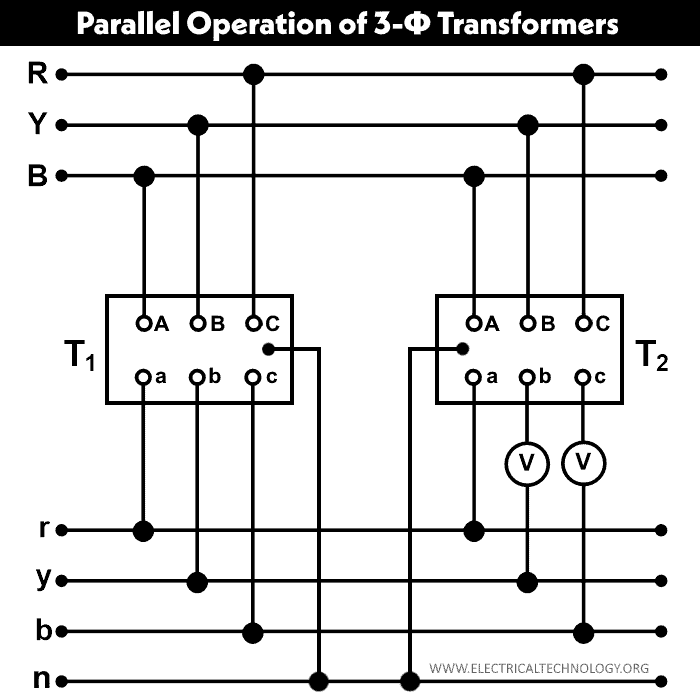
The primary and secondary winding of both transformers (T1 and T2) are connected as shown in the above figure. Here, the b and c terminals of the secondary winding are kept flexible and connected with a voltmeter for testing purposes. If both voltmeters show zero reading, the polarities are correct. If the voltmeter shows twice of phase voltages, the polarities are wrong.
- Transformer Phasing: The Dot Notation and Dot Convention
- Transformers Fire Protection System – Causes, Types & Requirements
- Current Transformers (CT) – Types, Characteristic & Applications
- Autotransformer – Its Types, Operation, Advantages and Applications
- What is Potential Transformer (PT)? Types & Working of Voltage Transformers
- Power Transformer Protection and Faults
- Transformer Performance & Electrical Parameters
- Transformers Insulation Materials in Oil-Immersed & Dry Type T/F
- Application of Transformer
- Transformer Losses – Types of Energy Losses in a Transformer
- EMF Equation of a Transformer
- Open Delta Connections of Transformers
- Transformer Formulas and Equations
- Electrical Transformer Symbols – Single Line Transformer Symbols
Electrical Technology
Related articles.


How to Size a Single Phase and Three Phase Transformer in kVA? Calculator

How to Calculate the Battery Charging Time & Battery Charging Current – Example

How To Calculate Your Electricity Bill. Electric Bill Calculator with Examples

How to Find the Proper Size of Wire & Cable In Metric & Imperial Systems

Thevenin’s Theorem. Step by Step Procedure with Solved Example

Automatic Street Light Control Circuit using LDR & Transistor BC 547
One comment.
what will happen if the conditions for paralleling two three phase transformers are not met, with mathematical proof.
Leave a Reply Cancel reply
Your email address will not be published. Required fields are marked *

DF-DETR: Dead fish-detection transformer in recirculating aquaculture system
- Published: 13 November 2024
- Volume 33 , article number 43 , ( 2025 )
Cite this article

- Tingting FU 1 , 2 , 3 , 4 ,
- Dejun Feng 1 ,
- Pingchuan Ma 2 , 3 , 4 ,
- Weichen Hu 2 , 3 , 4 ,
- Xinting Yang 2 , 3 , 4 ,
- Shantan Li 1 , 2 , 3 , 4 &
- Chao Zhou 2 , 3 , 4
In aquaculture, real-time and rapid detection of dead fish is important for early risk warning and improving aquaculture efficiency. However, the complex actual environment and uncontrollable fish movement have brought great challenges to the detection of dead fish. Therefore, this paper proposes a high-precision and lightweight dead fish-detection transformer (DF-DETR) based on machine vision and original RT-DETR (real-time detection transformer). The specific implementation is as follows: Firstly, the backbone of the original RT-DETR was replaced by the RepNCSPELAN module which extracts multi-scale features. This not only improves the model’s ability to detect targets of different sizes but also reduces the amount of model parameters. Secondly, the AIFI in the RT-DETR was improved to CascadedGroupAttention (CGA). By changing the original feature fusion method, different levels of features are grouped and attention mechanism is added, so as to capture more target features. Finally, the CCFM_CSP module was constructed to fuse important features using parallel dilated convolution with different expansion rates, which improves the detection accuracy. The experimental results show that the [email protected] of the proposed dead fish detection model DF-DETR can reach 96.6%, and the parameter amount is reduced by 27% compared with the original RT-DETR. In summary, the proposed DF-DETR model realizes real-time and high-precision dead fish detection, which can provide effective technical support for the development of intelligent inspection robots.
This is a preview of subscription content, log in via an institution to check access.
Access this article
Subscribe and save.
- Get 10 units per month
- Download Article/Chapter or eBook
- 1 Unit = 1 Article or 1 Chapter
- Cancel anytime
Price includes VAT (Russian Federation)
Instant access to the full article PDF.
Rent this article via DeepDyve
Institutional subscriptions

Data Availability
No datasets were generated or analysed during the current study.
Barbedo JGA (2022) A review on the use of computer vision and artificial intelligence for fish recognition, monitoring, and management. Fishes 7:335. https://doi.org/10.3390/fishes7060335
Article Google Scholar
Bochkovskiy A, Wang CY, Liao HYM (2020) YOLOv4: optimal speed and accuracy of object detection. ArXiv. abs/2004.10934. https://doi.org/10.48550/arXiv.2004.10934
Cao S, Zhao D, Liu X, Sun YJC (2020) Real-time robust detector for underwater live crabs based on deep learning. Electronics in Agriculture. 172:105339. https://doi.org/10.1016/j.compag.2020.105339
Chitmanat C, Pimpimol T, Chaibu P (2015) Investigation of bacteria and fish pathogenic bacteria found in freshwater aquaponic system. Agricultural Science. 7:254. https://doi.org/10.5539/jas.v7n11p254
Debnath SC, McMurtrie J, Temperton B, Delamare-Deboutteville J, Mohan CV, Tyler CR (2023) Tilapia aquaculture, emerging diseases, and the roles of the skin microbiomes in health and disease. Aquacult Int 31:2945–2976. https://doi.org/10.1007/s10499-023-01117-4
Girshick R, Donahue J, Darrell T, Malik J (2014) Rich feature hierarchies for accurate object detection and semantic segmentation. IEEE Computer Society. 580–587. https://doi.org/10.1109/CVPR.2014.81
Hao Y, Guo S, Zhou X, Yin H (2024) Underwater swimming fish mass estimation based on binocular vision. Aquacult Int. https://doi.org/10.1007/s10499-024-01550-z
Li X, Hao Y, Zhang P, Akhter M, Li D (2022) A novel automatic detection method for abnormal behavior of single fish using image fusion. Computers Electronics in Agriculture 203:107435. https://doi.org/10.1016/j.compag.2022.107435
Li Y, Hu Z, Zhang Y, Liu J, Tu W, Yu H (2024) DDEYOLOv9: network for detecting and counting abnormal fish behaviors in complex water environments. Fishes 9:242. https://doi.org/10.3390/fishes9060242
Li H, Xiong P, An J, Wang L (2018) Pyramid attention network for semantic segmentation. ArXiv. abs/1805.10180. https://doi.org/10.48550/arXiv.1805.10180
Liu C, Wang Z, Li Y, Zhang Z, Li J, Xu C et al (2023a) Research progress of computer vision technology in abnormal fish detection. Aquacult Eng 103:102350. https://doi.org/10.1016/j.aquaeng.2023.102350
Liu X, Peng H, Zheng N, Yang Y, Hu H, Yuan Y (2023b) EfficientViT: memory efficient vision transformer with cascaded group attention. IEEE/CVF Conference on Computer Vision and Pattern Recognition (CVPR). 14420–14430. https://doi.org/10.1109/cvpr52729.2023.01386
Lv W, Xu S, Zhao Y, Wang G, Wei J, Cui C et al (2023) DETRs beat YOLOs on real-time object detection. ArXiv. abs/2304.08069. https://doi.org/10.48550/arXiv./2304.08069v3
Lyu C, Zhong W-C, Liu S (2024) Improved YOLOv5s for typical carp target detection. Aquacult Int. https://doi.org/10.1007/s10499-024-01405-7
Redmon J, Farhadi A (2017) YOLO9000: better, faster, stronger. IEEE Conference on Computer Vision & Pattern Recognition. 6517–6525. https://doi.org/10.1109/CVPR.2017.690
Redmon J, Farhadi A (2018) YOLOv3: an incremental improvement. ArXiv. abs/1804.02767. https://doi.org/10.48550/arXiv.1804.02767
Redmon J, Divvala S, Girshick R, Farhadi A (2016) You only look once: unified, real-time object detection. Computer Vision & Pattern Recognition. 779–788. https://doi.org/10.1109/CVPR.2016.91
Ren S, He K, Girshick R, Sun J (2017) Faster R-CNN: towards real-time object detection with region proposal networks. IEEE Transactions on Pattern Analysis Machine Intelligence 39:1137–1149. https://doi.org/10.1109/TPAMI.2016.2577031
Article PubMed Google Scholar
Ross G (2015) Fast R-CNN. Computer science international conference on computer vision. IEEE Computer Society. 1440–1448. https://doi.org/10.1109/ICCV.2015.169
Schmidhuber J (2014) Deep learning in neural networks: an overview. Neural Networks: the Official Journal of the International Neural Network Society 61:85–117. https://doi.org/10.1016/j.neunet.2014.09.003
Wang JH, Lee SK, Lai YC, Lin CC, Chiang CP (2020b) Anomalous behaviors detection for underwater fish using AI techniques. IEEE Access 8:1–1. https://doi.org/10.1109/access.2020.3043712
Wang C, Li Z, Wang T, Xu X, Zhang X, Li D (2021) Intelligent fish farm-the future of aquaculture. Aquacult Int 29:2681–2711. https://doi.org/10.1007/s10499-021-00773-8
Article CAS Google Scholar
Wang CY, Liao HYM, Wu YH, Chen PY, Yeh IH (2020a) CSPNet: a new backbone that can enhance learning capability of CNN. IEEE/CVF Conference on Computer Vision and Pattern Recognition Workshops (CVPRW). 1571–1580. https://doi.org/10.1109/cvprw50498.2020.00203
Wang C-Y, Liao H-YM, Eng I-HYJJIS (2022a) Designing network design strategies through gradient path analysis. ArXiv. 39. https://doi.org/10.6688/jise.202307
Wang C-Y, Yeh I-H, Liao H (2024) YOLOv9: learning what you want to learn using programmable gradient information. ArXiv. abs/2402.13616. https://doi.org/10.48550/arXiv.2402.13616
Wang H, Zhang S, Zhao S, Lu J, Wang Y, Li D et al (2022b) Fast detection of cannibalism behavior of juvenile fish based on deep learning. Comput Electron Agric 198:107033. https://doi.org/10.1016/j.compag.2022.107033
Wang H, Zhang S, Zhao S, Wang Q, Li D, Zhao R (2022c) Real-time detection and tracking of fish abnormal behavior based on improved YOLOV5 and SiamRPN++. Computers Electronics in Agriculture 192:106512. https://doi.org/10.1016/j.compag.2021.106512
Wei L, Dragomir A, Dumitru E, Christian S, Scott R, Cheng-Yang F et al (2016) SSD: single shot multibox detector. European Conference on Computer Vision. 21–37. https://doi.org/10.1007/978-3-319-46448-0_2
Xie Y, Xiang J, Li X, Yang C (2024) An intelligent fishery detection method based on cross-domain image feature fusion. Fishes 9:338. https://doi.org/10.3390/fishes9090338
Yang X, Zhang S, Liu J, Gao Q, Dong S, Zhou C (2020) Deep learning for smart fish farming: applications, opportunities and challenges. Rev Aquac 13:66–90. https://doi.org/10.1111/raq.12464
Ye Z, Zhou J, Ji B, Zhang Y, Peng Z, Ni W et al (2024) Feature fusion of body surface and motion-based instance segmentation for high-density fish in industrial aquaculture. Aquacult Int. https://doi.org/10.1007/s10499-024-01569-2
Zhang M, Yang H, Li P, Jiang M (2022) Human pose estimation based on parallel atrous convolution and body structure constraints. Applications in Engineering Technology 42:5553–5563. https://doi.org/10.3233/jifs-212061
Zhang L, Liu Z, Zheng Y, Li B (2024) Feeding intensity identification method for pond fish school using dual-label and MobileViT-SENet. Biosys Eng 241:113–128. https://doi.org/10.1016/j.biosystemseng.2024.03.010
Zhao S, Zhang S, Lu J, Wang H, Feng Y, Shi C et al (2022) A lightweight dead fish detection method based on deformable convolution and YOLOV4. Comput Electron Agric 198:107098. https://doi.org/10.1016/j.compag.2022.107098
Zhou C, Xu D, Lin K, Sun C, Yang X (2017) Intelligent feeding control methods in aquaculture with an emphasis on fish: a review. Rev Aquac 10:975–993. https://doi.org/10.1111/raq.12218
Download references
This study was supported by the National Key R & D Program of China (2022YFD2001701) and the National Natural Science Foundation of China (32373184).
Author information
Authors and affiliations.
Zhejiang Ocean University, Zhejiang, 316000, China
Tingting FU, Dejun Feng & Shantan Li
National Engineering Laboratory for Agri-Product Quality Traceability, Beijing, 100097, China
Tingting FU, Pingchuan Ma, Weichen Hu, Xinting Yang, Shantan Li & Chao Zhou
Information Technology Research Center, Beijing Academy of Agriculture and Forestry Sciences, Shuguang Huayuan Middle Road 9#, Haidian District, Beijing, 100097, China
National Engineering Research Center for Information Technology in Agriculture, Beijing, 100097, China
You can also search for this author in PubMed Google Scholar
Contributions
Tingting Fu: Conceptualization, Methodology, Software, Investigation, Formal analysis, Writing-original draft. Dejun Feng: Visualization, Investigation. Pingchuan Ma: Data curation, Writing – original draft. Weicheng Hu: Resources, Supervision. Xinting Yang: Software, Validation. Shantan Li: Resources, Validation. Chao Zhou: Conceptualization, Funding acquisition, Resources, Supervision, Writing-review & editing.
Corresponding author
Correspondence to Chao Zhou .
Ethics declarations
Competing interest.
The authors declare no competing interests.
Additional information
Handling Editor: Sara Pinho
Publisher's Note
Springer Nature remains neutral with regard to jurisdictional claims in published maps and institutional affiliations.
Rights and permissions
Springer Nature or its licensor (e.g. a society or other partner) holds exclusive rights to this article under a publishing agreement with the author(s) or other rightsholder(s); author self-archiving of the accepted manuscript version of this article is solely governed by the terms of such publishing agreement and applicable law.
Reprints and permissions
About this article
FU, T., Feng, D., Ma, P. et al. DF-DETR: Dead fish-detection transformer in recirculating aquaculture system. Aquacult Int 33 , 43 (2025). https://doi.org/10.1007/s10499-024-01697-9
Download citation
Received : 09 July 2024
Accepted : 09 October 2024
Published : 13 November 2024
DOI : https://doi.org/10.1007/s10499-024-01697-9
Share this article
Anyone you share the following link with will be able to read this content:
Sorry, a shareable link is not currently available for this article.
Provided by the Springer Nature SharedIt content-sharing initiative
- Dead fish detection
- Feature fusion
- Recirculating aquaculture system
- Find a journal
- Publish with us
- Track your research

IMAGES
VIDEO
COMMENTS
Parallel operation of transformers is used for load sharing. The transformers are connected in parallel on both primary and secondary side. Following conditions to be satisfied during the parallel operation of transformers. Same polarities should be connected. The two transformers should have same voltage ratio. The percentage impedance should ...
Experiment Name: Polarity Test for Operation of Two Single Phase Transformers in Parallel. Objective: To test polarity of two single phase transformers. Theory: We do polarity test on parallel transformers to ensure that we connect the same polarity windings and not the opposite ones. If we accidentally connect the opposite polarities of the ...
In this video I have shown, the Parallel Operation of Two Single Phase Transformers and Load Sharing🎥 Watch Related Videos :_____Polari...
In this electrical machines lab experiment parallel operation of two single phase transformers has been performed. #engineeringdevotion
In this video, I have shown how to make connections for two transformers to be connected in parallel.Video done by Abhijit and done under the supervision of ...
The per unit impedances of two transformers on their respective Z bases must be equal if the trans- formers have to share the load in proportion to their ratings Under parallel operation, the two transformers would share the total load current as indicated in Figure 2: Equivalent Circuit of Two Single-phase Transformers in Parallel Fig.2.
Following conditions to be satisfied during the parallel operation of transformers-. The two transformers should have same voltage ratio. Connect all the apparatus as per circuit diagram (fig. 11.1) for polarity test. Measure the terminal voltage. if voltage is zero then the polarity is same. Again connect all the apparatus as per circuit ...
Parallel Operation of a Single Phase Transformer means that the two or more transformers having the same polarities, same turn ratios, same phase sequence and the same voltage ratio are connected in parallel with each other. The circuit diagram of two single-phase transformer A and B connected in parallel are shown below:
May 8, 2024 by Electrical4U. Contents. 💡. Key learnings: Parallel Operation Defined: Parallel operation of transformers is when multiple transformers are connected to increase system reliability, efficiency, and flexibility. Maximizing Efficiency: Efficient parallel operation is achieved by activating only the transformers necessary to meet ...
By parallel operation of single-phase transformers, we mean two or more transformers are connected to the same supply bus bars on the primary side and to a common bus bar/load on the secondary side. Such a requirement is frequently encountered in practice. Two transformers A and B connected in parallel are shown in the figure. While connecting ...
E. What will happen if two transformers are connected in parallel with wrong polarity? ..... 8. Conclusions Write in your own words the conclusion of performing this experiment. Write about what you learned from this experiment, what you can tell about the parallel operation of two single phase transformer that you did in experiment.
Parallel Operation of Single-Phase Transformer. Two single-phase transformers can be connected in parallel as shown in the figure below. As shown in the figure, the primary winding of both transformers is connected with the supply bus bar and the secondary winding of both transformers is connected with the load bus bar.
PDF-1.4 %µµµµ 1 0 obj >/OutputIntents[>] /Metadata 1806 0 R>> endobj 2 0 obj > endobj 3 0 obj >/XObject >/ProcSet[/PDF/Text/ImageB/ImageC/ImageI] >>/MediaBox[ 0 0 ...
Conditions for satisfactory parallel operation of transformers # Load sharing in transformers connected in parallelLink to download the PDF file of PPT: http...
2. To perform Load test on a single phase transformer. 3. To separate core losses of single phase transformer at no-load. 4. To perform parallel operation of two single phase transformers. 5. To study the various connections of three phase transformer. 6. To perform Scott connections on three phase transformer to get two phase supply. 7.
To successfully operate the transformers in parallel, while commissioning, certain rules must be followed. We state them below, as applied to the single-phase transformers used in the experiment. Requirements for Parallel Operation of Two Single-phase Transformers. Figure 1 Conceptual Diagram of Two single-phase Transformers in Parallel
A single-phase version is chosen for the sake of simplicity and to allow for a direct comparison with a diesel generator in residential applications, as displayed in Figure 1b. This comparison is due to the fact that diesel generators are actually the traditional and accessible way to generate electricity in sectors that do not have access to ...
Demonstration of Parallel Operation of Two Single-Phase Transformers#engineeringdevotion
In aquaculture, real-time and rapid detection of dead fish is important for early risk warning and improving aquaculture efficiency. However, the complex actual environment and uncontrollable fish movement have brought great challenges to the detection of dead fish. Therefore, this paper proposes a high-precision and lightweight dead fish-detection transformer (DF-DETR) based on machine vision ...